Variable frequency drive for AC induction motor
This is a VFD design available as open hardware. It has some caveats -- it's not a true bullet-proof industry-strength VFD, but it works as a driver for a low power 200W motor and can be extended.
The story began when my friend offered me to take a part in building a throwing wheel for another friend of ours. I'm fairly new to electronics and have never built any high power device, so it was a challenge for me.
Then I've got a comment to one of my posts that was posted on hackaday.com - it was from Ryan Gibson, SEO consultant at farnell.com. After some googling I've found many similar comments on other blogs, it sounded like some spam scheme, but I responded anyway. And it seems that Ryan Gibson is legit! I got an offer from farnell.com to order
some free stuff in exchange for a blog post. So here it goes :)
I've got MC3PHAC as a controller and IRAMS06UP60A as a power stage from farnell.com.
The driver is straight forward - MC3PHAC generates six PWM channels that are fed to IRAMS06UP60A which uses PWM to open and close three IGBT half bridges to drive three phases of motor. If you are interested, there are vast amounts of pages that explain how all this works and how AC induction motor works. MC3PHAC has options to select frequency of mains power for which the motor was built, PWM frequency, dead time, PWM polarity, acceleration and speed. IRAMS06UP60A is a power stage, it has thermal shutdown protection built in, the same pin of it can be used for over-current protection shutdown.
After more googling i've found out that it's fairly easy to toast a power stage in the same combination of controller and power driver as mine so i put some effort in following datasheets and application notes as closely as possible, so here goes my insights:
- add pullups or pulldowns (depending of PWM polarity of power stage inputs) to outputs of controller so inputs of power stage are never left floating.
- calculate size and power capabilities of DC bus decoupling capacitor. This is a good paper explaining everything about the matter: Selecting Film Bus Link Capacitors
For High Performance Inverter Applications
- if motor in your application can work as a voltage generating device, add a DC bus over voltage protection (MC3PHAC has a DC bus voltage sense pin and Rbrake pin for that) -- add a resistor divider to scale DC bus voltage down to level acceptable by controller. Or you could use a varistor across DC bus.
- put in EMI filters. I used this app note: Design of the Inverter Output Filter for Motor
Drives with IRAMS Power Modules
- add overcurrent protection. Because the power of the motor i was using is relatively low, and i was already eager to build something, i've omited low side current sensing opamp over shunt resistor leaving that for v2 or the driver.
- MC3PHAC is VERY picky about clock source, i've tried zillion crystal and load cap combinations and couldn't get it to work untill i got an exact crystal resonator as specified in datasheet.
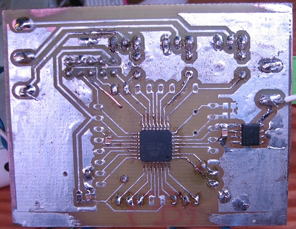
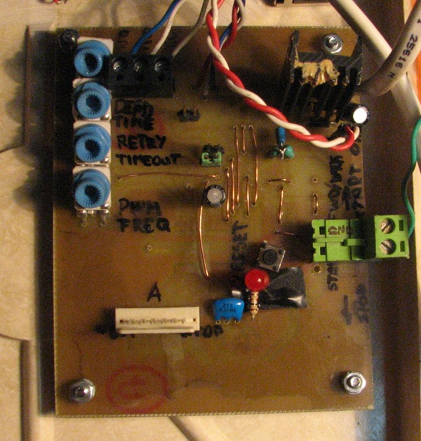
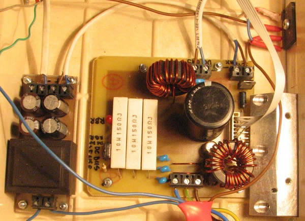
The driver board:
The power stage board
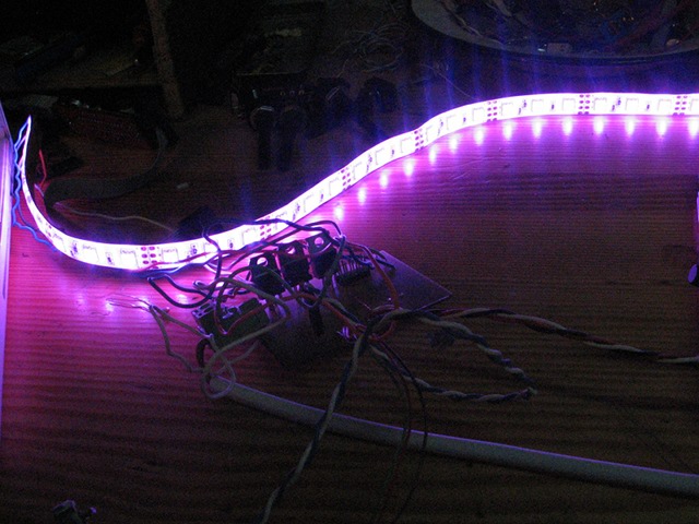
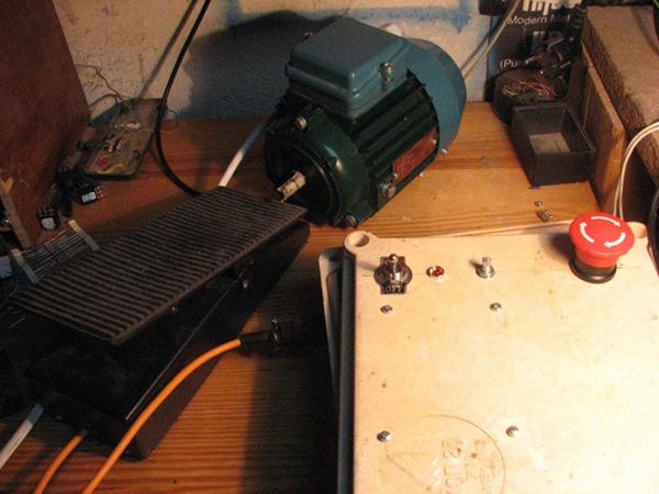
The whole setup view:
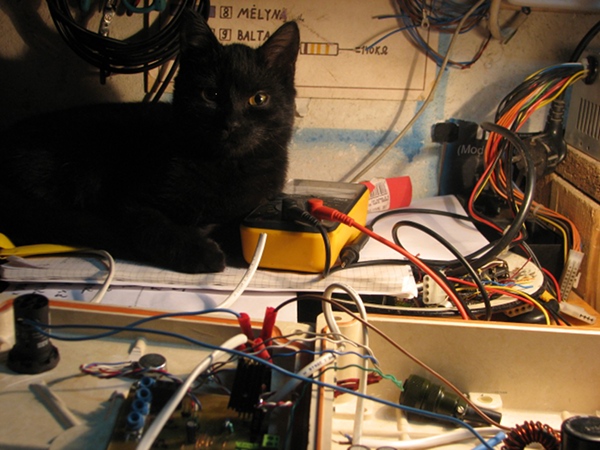
Zalgo cat is helping me to debug:
The eagle files to download:
Download controller schematics
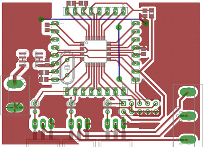
Download controller pcb
Download power stage schematics
Download poer stage pcb
Download power source schematics
Download power source pcb
Shematics and PCB in png format: